Monday, July 13, 2015

2.4.3. Standard Penetration Test ASTM D1586-11


There are several different types of field tests that can be performed at the time of drilling. For exam-ple, the SPT consists of driving a thick-walled sampler in order to determine the driving resistance
of the soil (see Fig. 2.10).


Test Procedure. The SPT can be used for all types of soil, but in general, the SPT is most often
used for sand deposits.

The SPT can be especially of value for clean sand deposits where the sand falls or flows out from the sampler when retrieved from the ground. 

Without a soil sample, other types of tests, such as the SPT, must be used to assess the engineering properties of the sand.

Often when drilling a borehole, if subsurface conditions indicate a sand strata and sampling tubes come up empty, the sampling gear can be quickly changed to perform SPT.

The system to drive the SPT sampler into the soil, known as the drive-weight assembly, basically
consists of:

  • the hammer
  • hammer fall guide
  • anvil
  • and a hammer release system
    SPT apparatus
Hammer. The metal hammer is successively lifted and dropped in order to provide the energy that
drives the SPT sampler into the ground.

Hammer Fall Guide. This part of the drive-weight assembly is used to guide the fall of the hammer as it strikes the anvil.

Anvil.  This is the portion of the drive-weight assembly which the hammer strikes and through
which the hammer energy is passed into the drill rods.

Hammer Release System. This is the part of the drive-weight assembly by which the operator lifts
and drops the hammer. Two types of systems are commonly utilized, as follows:

1.The first hammer release system is the trip, automatic, or semiautomatic system, where the ham-mer is lifted and allowed to drop unimpeded.

2.The second hammer release system is commonly referred to as the cathead release system. It is a
method of raising and dropping the hammer that uses a rope slung through a center crown sleeve
or pulley on the drill rig mast and turns on a cathead to lift the hammer. 

The cathead is defined as a spinning sleeve or rotating drum around which the drill rig operator wraps the rope used to lift and drop the hammer by successively tightening and loosening the rope turns around the drum. 

The drill rig operator should use two rope turns on the cathead when lifting the hammer because more than two rope turns on the cathead impedes the fall of the hammer

SPT procedure
There are many different types of hammers utilized for the SPT. 

A commonly used hammer type is the safety hammer, which is defined as a drive-weight assembly consisting of a 
  • center guide rod
  •  internal anvil
  •  and hammer that encloses the hammer-anvil contact. 

Typical internal designs of safety hammers are shown in ASTM D 6066-96 (2004).

Per ASTM D 1586-11, “Standard Test Method for Penetration Test and Split-Barrel Sampling
of Soils,” sampler dimensions and test parameters for the SPT must be as follows:

Sampler inside tube diameter =1.5 in. (3.81 cm), see Fig. 2
Sampler outside tube diameter =2.0 in. (5.08 cm), see Fig. 2
• Sampler is driven by a metal drop hammer that has a weight of 140 lb. (63.5 kg) and a free-fall dis-tance of 30 in. (0.76 m)
• Sampler is driven a total of 18 in. (45 cm), with the number of blows recorded for each 6 in. (15 cm)
interval
The measured N value (blows per ft) is defined as the penetration resistance, which equals the
sum of the number of blows needed to drive the SPT sampler over the depth interval of 6 to 18 in. (15 to 45 cm). 

The reason the number of blows required to drive the SPT sampler for the first 6 in.
(15 cm) is not included in the Nvalue is because the drilling process often disturbs the soil at the
bottom of the borehole and the readings from 6 to 18 in. (15 to 45 cm) are believed to be more rep-resentative of the in situ penetration resistance of the sand.
  • It is desirable to apply hammer blows at a rate of about 20 to 40 blows per min. 
  • After performing the SPT, the minimum recommended borehole cleanout is 1 ft (0.3 m). 


Thus, since the SPT itself requires 1.5 ft (0.46 m) of penetration, the minimum vertical spacing between tests is 2.5 ft (0.76 m).

Often a larger vertical spacing of 3 to 5 ft (0.9 to 1.5 m) is used between each SPT.
SPT procedure

Factors that Can Affect the SPT

 The measured Nvalue can be influenced by the type of soil, such as the amount of fines and gravel size particles in the soil. 

Saturated sands that contain appreciable fine soil particles, such as silty or clayey sands, could give abnormally high Nvalues if they have a tendency to dilate or abnormally low Nvalues if they have a tendency to contract during the undrained shear conditions associated with driving the SPT sampler. 

Gravel size particles increase the driving resistance (hence increased Nvalue) by becoming stuck in the SPT sampler tip or barrel.

A factor that could influence the measured Nvalue is groundwater. 

It is important to maintain a level of water in the borehole at or above the in situ groundwater level. 

This is to prevent groundwater from rushing into the bottom of the borehole, which could loosen the sand and result in low measured Nvalues.

Besides soil and groundwater conditions described earlier, there are many different testing factors
that can influence the accuracy of the SPT readings (see Table 2.5). 

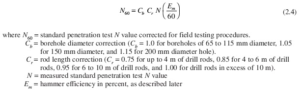
For example, the hammer efficiency, borehole diameter, and the rod lengths could influence the measured Nvalue. 

The following equation is used to compensate for these testing factors by multiplying together four factors as follows (Skempton, 1986):


The theoretical energy that should be delivered to the top of the anvil is 350 ft-lb of energy (i.e.,
140 lb times 30 in. drop). 

However, the SPT theory has evolved around the concept that about 60 percent of the hammer energy should be delivered to the drill rods, with the rest being dissipated through friction and hammer rebound.

Using the cathead release system and a safety hammer will deliver about 60 percent (i.e., Em = 60) of the hammer energy to the drill rods. 
Note in Eq. 2.4 that if Em = 60, no correction is required to the Nvalue for hammer efficiency.

Studies have shown that the cathead release system and a donut hammer can impart only 45 percent of the theoretical energy to the drill rods (i.e., Em = 45). 

At the other extreme are automatic systems that lift the hammer and allow it to drop unimpeded and deliver higher energy to the drill rods with values of Em as high as 95 percent being reported (ASTM D 6066-96, 2004). 

For other types of release systems and hammers, values of Em should be based on manufacturer specifications or pre-viously published measurements.

Even with this hammer energy uncertainty, the SPT is still probably the most widely used field
test in the United States. This is because:
  • it is relatively easy to use, 
  • the test is economical as compared to other types of field testing,
  • and the SPT equipment can be quickly adapted and included as part of almost any type of drilling rig.


The (N1)60 value (blows per foot) can also be used as a guide in determining the density condition of a clean sand deposit (see Table 2.6). 

Note that this correlation is very approximate and the boundaries between different density conditions are not as distinct as implied by Table 2.6. 


If(N1)60 =2 or less, then the sand should be considered to be very loose and could be subjected to significant settlement due to the weight of a structure or due to earthquake shaking.

On the otherhand, if (N1)60 =35 or more, then the sand is considered to be in a very dense condition and would be able to support high foundation loads and would be resistant to settlement from earthquake shaking.

For further details on determining the (N1)60 value for use in liquefaction studies, see ASTM D
6066-96 (2004), “Standard Practice for Determining the Normalized Penetration Resistance of
Sands for Evaluation of Liquefaction Potential.”


SUMMING UP:
A common soils test is the standard penetration test (SPT), which is performed in situ as part of the drilling and sampling operation. (The term“in situ”is synonymous with“in place.”) 

The SPT measures resistance to the penetration of a standard split-spoon sampler that is driven by a 140 lbm (63.5 kg) hammer dropped from a height of 30 in (0.76 m). 

The number of blows required to drive the sampler a distance of 12 in (0.305 m) after an initial penetration of 6 in (0.15 m) is referred to as theN-value or standard penetration resistance in blows
per foot.

The measured value of N is inconsistent from operator to operator because different drill rig systems deliver energy input that deviates from the theoretical value.

Therefore, the N-value obtained in the field is converted to a standardized N-value, N'.

In addition, because the N-value is sensitive to overburden pressure, corrections are applied to reference the value to a standard overburden stress, usually 2000 lbf/ft2 (95.76 kPa).

TheN-value has been correlated with many other mechanical properties, including shear modulus, unconfined compressive strength, angle of internal friction, and relative density. The correlations work best with cohesionless soils.
Table 35.9 relates N to the relative density and friction angle.


Thursday, July 9, 2015

2.4.2 Sample disturbance

This section will discuss the three types of soil samples that can be obtained during the subsurface
exploration.

In addition, this section will also discuss:

  • sampler and sample ratios used to evaluate sample disturbance; 
  • factors that affect sample quality
  • and transporting, preserving, and disposal of soil samples.

Types of soil samples

There are three types of soil samples that can be recovered from borings:

Altered Soil (also known as Nonrepresentative Samples).  During the boring operations, soil can
be altered due to

  • mixing or 
  • contamination. 


Such materials do not represent the soil found at the bottom of the borehole and hence should not be used for visual classification or laboratory tests.

Some examples of altered soil are as follows:


  • Failure to clean the bottom of the boring.  If the boring is not cleaned out prior to sampling, a soil sample taken from the bottom of the borehole may actually consist of cuttings from the side of the borehole. These borehole cuttings, which have fallen to the bottom of the borehole, will not represent in situ conditions at the depth sampled.


  • Soil contamination.  In other cases, the soil sample may become contaminated with drilling fluid, which is used for wash-type borings.


mud


  • Soil mixing.  Soil or rock layers can become mixed during the drilling operation, such as by the action of a flight auger.  For example, suppose varved clay, which consists of thin alternating layers of sand and clay, becomes mixed during the drilling and sampling process. Obviously laboratory tests would produce different results when performed on the mixed soil as compared to laboratory tests performed on the individual sand and clay layers.

Flight auger

  • Change in moisture content.  Soil that has a change in moisture content due to the drilling fluid or from heat generated during the drilling operations should also be classified as altered soil.


  • Densified soil.  Soil that has been densified by over-pushing or over-driving the soil sampler should also be considered as altered because the process of over-pushing or over-driving could squeeze water from the soil.                                                                                                   Figure 2.12 shows a photograph of the rear end of a Shelby tube sampler. The soil in the sampler has been densified by being over-pushed as indicated by the smooth surface of the soil and the mark in the center of the soil (due to the sampler head).


Disturbed Samples (also known as Representative Samples).  It takes considerable experience and
judgment to distinguish between altered soil and disturbed soil.

In general, disturbed soil is defined as soil that has not been contaminated by material from other strata or by chemical changes, but the soil structure is disturbed and the void ratio may be altered.

In essence, the soil has only been remolded during the sampling process.

For example, soil obtained from driven thick-walled samplers, such as

  •  the SPT spilt spoon sampler, 
  • or chunks of intact soil brought to the surface in an auger bucket (i.e., bulk samples) 

are considered disturbed soil.

Disturbed soil can be used for:
  • visual classification 
  • as well as numerous types of laboratory tests.

Example of laboratory tests that can be performed on disturbed soil include

  • water content, 
  • specific gravity, 
  • Atterberg limits, 
  • sieve and hydrometer tests, 
  • expansion index test, 
  • chemical composition (such as soluble sulfate), 
  • and laboratory compaction tests such as the Modified Proctor.

SPT disturbed sample
Undisturbed Samples.  Undisturbed samples may be broadly defined as soil that has been subjected to no disturbance or distortion and the soil is suitable for laboratory tests that measure;
  • the shear strength,
  • consolidation, 
  • permeability, 
  • and other physical properties of the in situ material. 

As a practical matter, it should be recognized that no soil sample can be taken from the ground and be in a perfectly undisturbed state. 

But this terminology has been applied to those soil samples taken by certain sampling methods. 

Undisturbed samples are often defined as those samples obtained by slowly pushing thin-walled
tubes, having sharp cutting ends and tip relief, into the soil.

Undisturbed soil samples are essential in many types of foundation engineering analyses, such as
the determination of allowable bearing pressure and settlement. 
undisturbed soil sample


Sampler and Sample Ratios Used to Evaluate Sample Disturbance

Figure 2.13 presents various sampler and sample ratios that are used to evaluate the disturbance potential of different samplers and of the soil samples themselves. 

For soil samplers, the two most important parameters to evaluate disturbance potential are
  • the inside clearance ratio 
  • and area ratio,

 defined as follows:

So that they can be expressed as a percentage, both the inside clearance ratio and area ratio are
typically multiplied by 100.

Note in Fig. 2.13 that because common terms cancel out, the area ratio can be defined as the volume of displaced soil divided by the volume of the sample.

In general, a sampling tube for undisturbed soil specimens should have:
  • an inside clearance ratio of about 1 percent 
  • and an area ratio of about 10 percent or less. 

Having an inside clearance ratio of about 1 percent provides for tip relief of the soil and reduces the friction between the soil and inside of the sampling tube during the sampling process. 

A thin film of oil can be applied at the cutting edge to also reduce the friction between the soil and metal tube during sampling operations. 

The purpose of having a low area ratio and a sharp cutting end is to slice into the soil with as little disruption and displacement of the soil as possible. 


  • Shelby tubes are manufactured to meet these specifications and are considered to be undisturbed soil samplers. 
  • As a comparison, the California sampler has an area ratio of 44 percent and is considered to be a thick-walled sampler.

Standard Practice for Thin-Walled Tube Sampling of Soils for Geotechnical Purposes (ASTM D1587)

TABLE 2 Suitable Thin-Walled Steel Sample TubesA
Outside diameter (Do):


 in.
 mm
2
50.8
3
76.2
5
127
Wall thickness:


 Bwg
18
16
11
 in.
0.049
0.065
0.120
 mm
1.24
1.65
3.05
Tube length:


 in.
 m
36
0.91
36
0.91
54
1.45
Inside clearance ratio, %
<1
<1
<1
A The three diameters recommended in Table 2 are indicated for purposes of standardization, and are not intended to indicate that sampling tubes of intermediate or larger diameters are not acceptable. Lengths of tubes shown are illustrative. Proper lengths to be determined as suited to field conditions.

Figure 2.13 also presents common ratios that can be used to assess the possibility of sample disturbance of the actual soil specimen. 

Examples include the 
  • total recovery ratio
  • specific recovery ratio
  • gross recovery ratio
  • net recovery ratio
  • and true recovery ratio. 

These disturbance parameters are based on the compression of the soil sample due to the sampling operations.
Because the length of the soil specimen is often determined after the sampling tube is removed from the borehole, a commonly used parameter is the gross recovery ratio, defined as:


where 
  • Lg is gross length of sample, which is the distance from the top of the sample to the cutting edge of the sampler after removal of the sampler from the boring (in. or cm).
  • H is depth of penetra-tion of the sampler, which is the distance from the original bottom of the borehole to the cutting edge of the sampler after it has been driven or pushed in place (in. or cm).


The closer the gross recovery ratio is to 1.0 (or 100 percent), the better the quality of the soil specimen.


                                            Factors that affect sample quality

It is important to understand that using a thin wall tube, such as a Shelby tube, or obtaining a gross recovery ratio of 100 percent would not guarantee an undisturbed soil specimen. 

Many other factors can cause soil dis-turbance, such as:

  • Pieces of hard gravel or shell fragments in the soil, which can cause voids to develop along the sides of the sampling tube during the sampling process
  • Soil adjustment caused by stress relief when making a borehole
  • Disruption of the soil structure due to hammering or pushing the sampling tube into the soil stratum
  • Tensile and torsional stresses which are produced in separating the sample from the subsoil
  • Creation of a partial or full vacuum below the sample as it is extracted from the subsoil
  • Expansion of gas during retrieval of the sampling tube as the confining pressure is reduced to zero
  • Jarring or banging the sampling tube during transportation to the laboratory
  • Roughly removing the soil from the sampling tube
  • Crudely cutting the soil specimen to a specific size for a laboratory test
The actions listed earlier cause a decrease in effective stress, a reduction in the interparticle bonds, and a rearrangement of the soil particles.

  • An “undisturbed” soil specimen will have little rearrangement of the soil particles and perhaps no disturbance except that caused by stress relief where there is a change from the in situ ko (at-rest) condition to an isotropic perfect samplestress condition 
  • A disturbed soil specimen will have a disrupted soil 
    structure with perhaps a total rearrangement of soil particles.

When measuring the shear strength or deformation characteristics of the soil, the results of laboratory tests run on 
undisturbed specimens obviously better represent in situ 
properties than laboratory tests run on disturbed specimens.

                                                                 Transporting Soil Samples

During transport to the laboratory, soil samples recovered from the
borehole should be kept within the sampling tube or sampling rings. In order to preserve soil sam-ples during transportation, the soil sampling tubes can be tightly sealed with end caps and duct tape.
Shelby tube samples
For sampling rings, they can be placed in cylindrical packing cases that are then thoroughly sealed.

Bulk samples can be placed in plastic bags, pails, or other types of waterproof containers. 

The goal of the transportation of soil samples to the laboratory is to prevent a loss of moisture. 

In addition, for  undisturbed soil specimens, they must be cushioned against the adverse effects of transportation induced vibration and shock. 

The soil samples should be marked with: 
  • the file or project number
  • date of sampling
  • name ofengineer or geologist who performed the sampling
  • boring number
  • depth
Other items that may need to be identified are as follows (ASTM D 4220-00, 2004):

1. Sample orientation (if necessary)
2. Special shipping and laboratory handling instructions
3. Penetration test data (if applicable)
4. Subdivided samples must be identified while maintaining association to the original sample
5. If required, sample traceability record

2.4.1. Soil and Rock samplers

There are many different types of samplers used to retrieve soil and rock specimens from the boring. For example, three types of soil samplers are shown in Fig. 2.10,

  • the California sampler
  • Shelby tube
  • and SPT sampler. 


One of the most important first steps in sampling is to clean-out the bottom of the borehole in order to remove the loose soil or rock debris that may have fallen to the bottom of the borehole.

For soil, the most common method is to force a sampler into the soil by either 
  • hammering, 
  • jacking, 
  • or pushing 

the sampler into the soil located at the bottom of the borehole. 

TYPES OF SAMPLERS FOR SOILS
Soil samplers are typically divided into two types: 


Thin-Walled Soil Sampler.  The most common type of soil sampler used in the United States is the
Shelby tube, which is a thin-walled sampling tube consisting of stainless steel or brass tubing. 

In order to slice through the soil, the Shelby tube has a sharp and drawn-in cutting edge. 

In terms of dimensions, typical 
  • diameters are from 2 to 3 in. (5 to 7.6 cm) 
  • and lengths vary from 2 to 3 ft (0.6 to 0.9 m)


The typical arrangement of 
  • drill rod
  • sampler head
  • and thin-wall tube sampler 

is shown in Fig. 2.11.


Shelby tube sampling

Shelby tube sampler

Shelby tube sample
The sampler head contains a ball check valve and vents for escape of air and water during
the sampling process.
The drill rig equipment can be used to either :
  • hammer
  •  jack
  • or push

 the sampler into the soil.

The preferred method is to slowly push the sampler into the soil by using hydraulic jacks or the weight of the drilling equipment.

Thin-walled soil samplers are used to obtain undisturbed soil samples
For further details on thin-walled sampling, see ASTM D 1587-00 (2004)


Thick-Walled Soil Sampler. Thin-walled samplers may not be strong enough to sample 
  • gravelly soils, 
  • very hard soils
  • or cemented soils. 

In such cases, a thick-walled soil sampler will be required.

Such samplers are often driven into place by using a drop hammer. 

The typical arrangement of 
  • drill rod
  • sampler head
  •  and barrel 

when driving a thick-walled sampler is shown in Fig. 2.11.

Many localities have developed thick-walled samplers that have proven successful for local con-ditions. 

For example, in southern California, a common type of sampler is the California sampler,
which is a split-spoon type sampler that contains removable internal rings, 
1.0 in. (2.54 cm) in height.

Figure 2.10 shows the California sampler in an open condition, with the individual rings exposed. 

The California sampler has a :
  • 3.0 in. (7.6 cm) outside diameter
  •  and a 2.50 in. (6.35 cm) inside diameter.


This sturdy sampler, which is considered to be a thick-walled sampler, has proven successful in
sampling  hard and desiccated soil and soft sedimentary rock common in southern California.

Another type of thick-walled sampler is the SPT sampler, which will be discussed in Sec. 2.4.3.
For further details on thick-walled sampling, see ASTM D 3550-01 (2004)
SPT sampler

SPT sampler


Wednesday, July 8, 2015

2.4. Borings

A boring is defined as a cylindrical hole drilled into the ground for the purposes of:

  • investigating sub-surface conditions
  • performing field tests
  • obtaining soil, rock, or groundwater specimens for testing
    .


Soil samples
    Field test (CBR in situ)


Borings can be excavated by hand (e.g., hand auger), although the usual procedure is to use mechanical equipment to excavate the borings
Hand Augers
STABILIZATION METHODS

During the excavation and sampling of the borehole, it is important to prevent caving-in of the
borehole sidewalls. In order to prevent the soil from caving-in there are many stabilization techniques used in practice such as:

  • Stabilization with Water.  Boreholes can be filled with water up to or above the estimated level of the groundwater table. This will have the effect of reducing the sloughing of soil caused by water rushing into the borehole. However, water alone cannot prevent caving-in of borings in soft or cohesionless soils or a gradual squeezing-in of a borehole in plastic soils. Uncased boreholes filled with water up to or above the groundwater table can generally be used in rock and for stiff to hard cohesive soils.
  • Stabilization with Drilling Fluid. An uncased borehole can often be stabilized by filling it with a properly proportioned drilling fluid, also known as “mud,” which when circulated also removes the ground-up material located at the bottom of the borehole. The stabilization effect of the drilling fluid is due to two effects: (1) the drilling fluid has a higher specific gravity than water alone, and (2) the drilling fluid tends to form a relatively impervious sidewall borehole lining, often referred to as mud-cake, which prevents sloughing of cohesionless soils and decreases the rate of swelling of cohesive soils. Drilling fluid is primarily used with rotary drilling and core boring methods.
  • Stabilization with Casing.  The safest and most effective method of preventing caving-in of the borehole is to use a metal casing. Unfortunately, this type of stabilization is rather expensive. The casing is usually driven in place by repeated blows of a drop hammer. It is often impossible to advance the original string of casing when difficult ground conditions or obstructions are encountered. A smaller casing is then inserted through the one in place, and the diameter of the extension of the borehole must be decreased accordingly.

TYPES OF BORINGS

There are many different types of equipment used to excavate borings. Typical types of borings include:

Auger boring.  A mechanical auger is the simplest and fastest method of excavating a boring. Because of these advantages, augers are probably the most common type of equipment used to excavate borings. The hole is excavated through the process of rotating the auger while at the same time applying a downward pressure on the auger to help penetrate the soil or rock. There are basically two types of augers: flight augers and bucket augers.
  • Bucket augers


  • Hollow-stem flight auger.  A hollow-stem flight auger has a circular hollow core, which allows for sampling down the center of the auger. The hollow-stem auger acts like a casing and allows for sampling in loose or soft soils or when the excavation is below the groundwater table.


Hollow-stem flight auger machine
    Hollow-stem flight auger (hollow core)

Wash boring.  A wash boring is advanced by the chopping and twisting action of a light bit (see fig. 2.5) and partly by the jetting of water, which is pumped through the hollow drill rod and bit.       The cuttings are removed from the borehole by the circulating water. Casing is typically required in soft or cohesionless soil, although it is often omitted for stiff to hard cohesive soil.


Wash boring setup


Rotary drilling.  For rotary drilling, the borehole is advanced by the rapid rotation of the drilling
bit that cuts, chips, and grinds the material located at the bottom of the borehole into small particles. In order to remove the small particles, water or drilling fluid is pumped through the drill rods and bit and ultimately up and out of the borehole. 
A drill machine and rig, such as shown in Fig. 2.6, are required to provide the rotary power and downward force required to excavate the boring. 


Percussion drilling.  This type of drilling equipment is often used to penetrate hard rock, for
subsurface exploration or for the purpose of drilling wells. The drill bit works much like a jack-hammer, rising and falling to break-up and crush the rock material. Percussion drilling works best
for rock and will be ineffective for such materials as soft clay and loose saturated sand.
In general, the most economical equipment for borings are truck mounted rigs that can quickly
and economically drill through hard or dense soil. 

It some cases, it is a trial and error process of using different drill rigs to overcome access problems or difficult subsurface conditions. 
For example, one deposit encountered by the author consisted of hard granite boulders surrounded by soft and highly plastic clay. The initial drill rig selected for the project was an auger drill rig, but the
auger could not penetrate through the granite boulders. The next drill rig selected was an air track
rig, which uses a percussion drill bit that easily penetrated through the granite boulders, but the soft
clay plugged up the drill bit and it became stuck in the ground. Over 50 ft (15 m) of drill stem could
not be removed from the ground and it had to be left in place, a very costly experience with diffi-cult drilling conditions.

Some of my other memorable experiences with drilling are as follows:

1.Drilling accidents.  Most experienced drillers handle their equipment safely, but accidents can
happen to anyone. One day, as I observed a drill rig start to excavate the hole, the teeth of the
auger bucket caught on a boulder. The torque of the auger bucket was transferred to the drill rig,
and it flipped over. Fortunately, no one was injured.

2.Underground utilities.  Before drilling, the local utility company, upon request, will locate their
underground utilities by placing ground surface marks that delineate utility alignments. An inci-dent involving a hidden gas line demonstrates that not even utility locators are perfect. On a par-ticularly memorable day, I drove a Shelby tube sampler into a 4 in. (10 cm) diameter pressurized
gas line. The noise of escaping gas was enough to warn of the danger. Fortunately, an experienced
driller knew what to do: turn off the drill rig and call 911.

3.Downhole logging.  As previously mentioned, a common form of subsurface exploration in
southern California is to drill a large-diameter boring, usually 30 in. (0.76 m) in diameter. Then
the geotechnical engineer or engineering geologist descends into the earth to get a close-up view
of soil conditions. On this particular day, several individuals went down the hole and noticed a
small trickle of water in the hole about 20 ft (6 m) down. The sudden and total collapse of the
hole riveted the attention of the workers, especially the geologist who had moments before been
down at the bottom of the hole.